
Evil Genius Labs
Purveyor of finely hand-crafted pixels. ꩜
Purveyor of finely hand-crafted pixels. ꩜

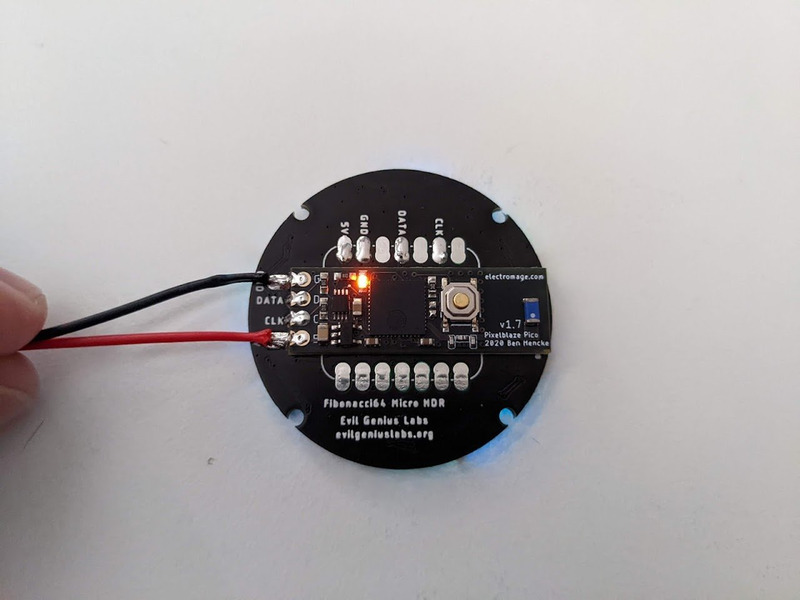
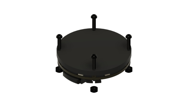
Fibonacci64 Micro HDR is a beautiful 40mm circular disc with 64 RGB LEDs surface mounted in a Fibonacci distribution. Swirling and pulsing like a miniature galaxy, it’s mesmerizing to watch.
It consists of 64 SK9822-EC2020 HDR (High Dymanic Range) RGB LEDs, arranged into a circular Fermat’s spiral pattern.

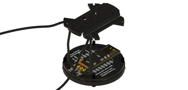
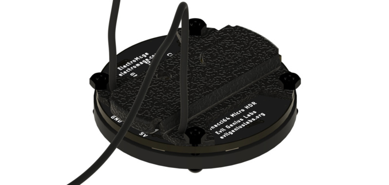
It has solder pads on the back that match the pinout of a Pixelblaze V3 Pico by ElectroMage, QT Py by Adafruit, or XIAO by Seeed. It can be used by any microcontroller via the 5V, GND, Clock and Data In pins.
In disc phyllotaxis, as in the sunflower and daisy, the mesh of spirals occurs in Fibonacci numbers because divergence (angle of succession in a single spiral arrangement) approaches the golden ratio. The shape of the spirals depends on the growth of the elements generated sequentially. In mature-disc phyllotaxis, when all the elements are the same size, the shape of the spirals is that of Fermat spirals—ideally. That is because Fermat's spiral traverses equal annuli in equal turns. The full model proposed by H Vogel in 1979[2] is


where θ is the angle, r is the radius or distance from the center, and n is the index number of the floret and c is a constant scaling factor. The angle 137.508° is the golden angle which is approximated by ratios of Fibonacci numbers.[3]
Fermat's spiral. (2015, October 24). In Wikipedia, The Free Encyclopedia. Retrieved 02:45, February 24, 2016, from https://en.wikipedia.org/w/index.php?title=Fermat%27s_spiral

Parts
Options available to purchase for additional amount:
If the “Fully Assembled” option is not chosen, these parts are not included, but are required to assemble and use:
Parts I used in my builds:
Open source touch demo: https://github.com/jasoncoon/fibonacci64-touch-demo/tree/f64-micro-hdr
Pixelblaze is an advanced WiFi LED pattern engine, created by ElectroMage. Live pattern expression compiler, lightning fast fixed point math, and HDR!
Fibonacci boards are laid out physically in a zig-zag pattern, from center to edge and back to center, all the way around the board. This layout automatically makes one dimensional patterns designed for strips visually interesting.
To treat the board as a matrix, you can use a pixel map. A 2D XY map can allow you to scroll colors, palettes, and patterns across the panel horizontally, vertically, diagonally, etc.
This map can be copied and pasted into the Pixel Mapper in the Mapper tab of your Pixelblaze web interface.
[[140,128],[189,114],[208,91],[214,63],[208,34],[146,0],[168,21],[180,48],[180,76],[162,106],[152,78],[146,47],[129,25],[103,11],[72,5],[40,38],[70,35],[97,42],[120,61],[131,101],[107,87],[79,69],[50,68],[23,78],[0,98],[7,143],[23,118],[46,102],[76,98],[93,122],[57,131],[37,152],[28,179],[29,209],[87,255],[68,230],[59,202],[62,174],[80,148],[113,142],[91,181],[94,210],[109,235],[133,252],[202,235],[172,234],[145,224],[125,203],[117,170],[145,183],[170,201],[198,205],[227,198],[253,181],[255,134],[235,157],[210,171],[181,173],[148,153],[175,145],[207,138],[228,120],[240,93],[244,63]]

Note: Double-check the position, alignment, and orientation of each component very carefully before soldering!
If you’re new to soldering, I highly recommend reading through a good soldering tutorial, such as the ones by Adafruit and SparkFun.