Evil Genius Labs
Purveyor of finely hand-crafted pixels. ꩜
Purveyor of finely hand-crafted pixels. ꩜


Retired
Alternatives:
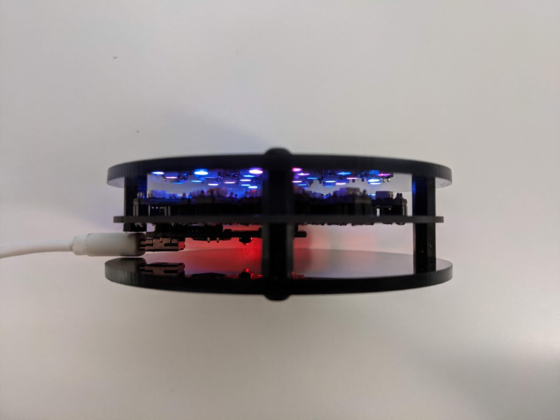
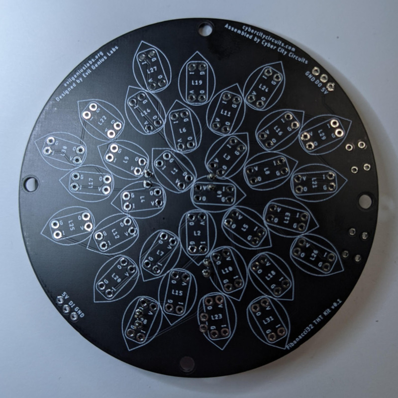
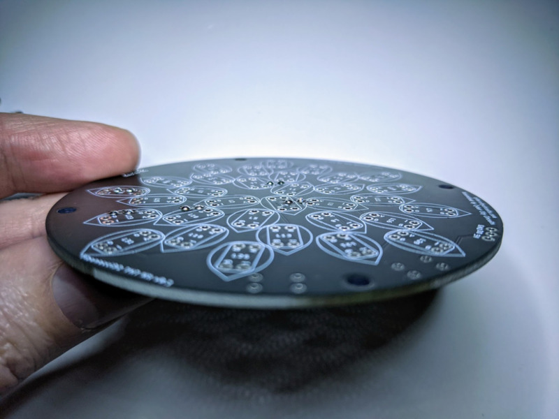
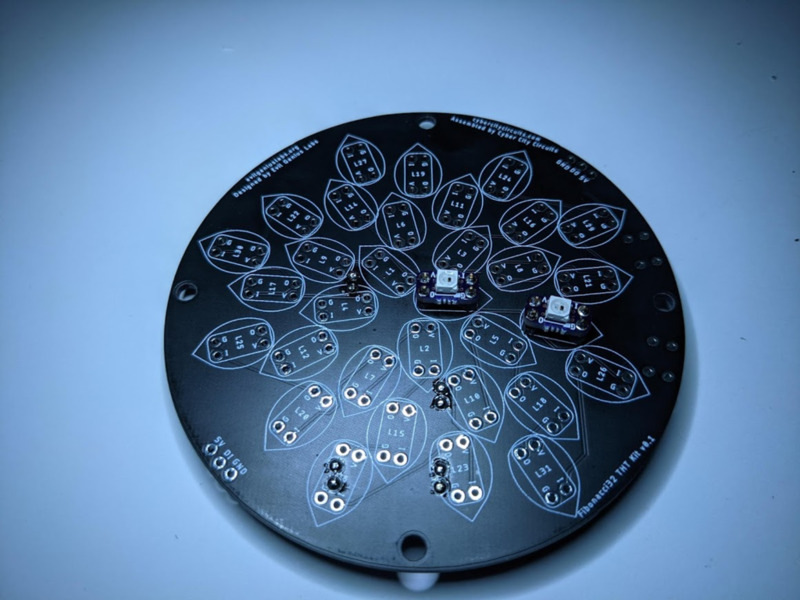
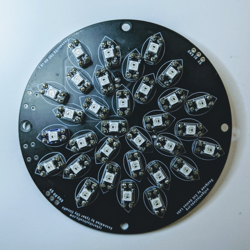
Fibonacci32 is a beautiful 86mm circular disc with 32 RGB LEDs surface mounted in a Fibonacci distribution. Swirling and pulsing like a colorful galaxy, it’s mesmerizing to watch.
It consists of 32 RGB LEDs, arranged into a circular Fermat’s spiral pattern.
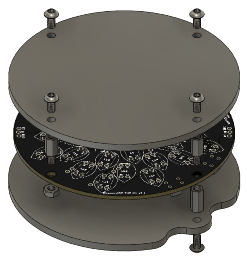
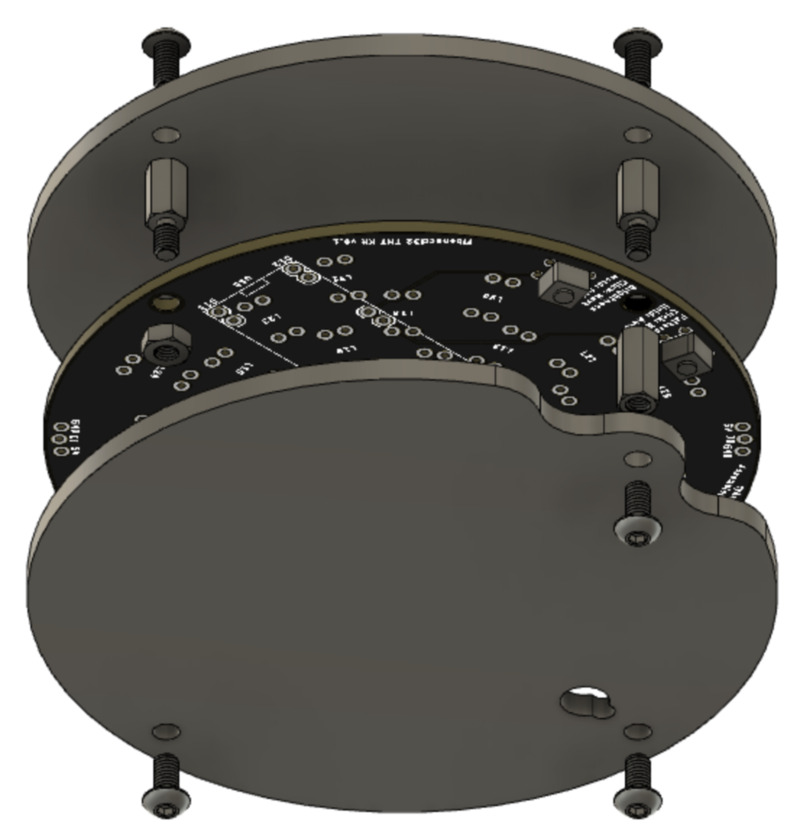
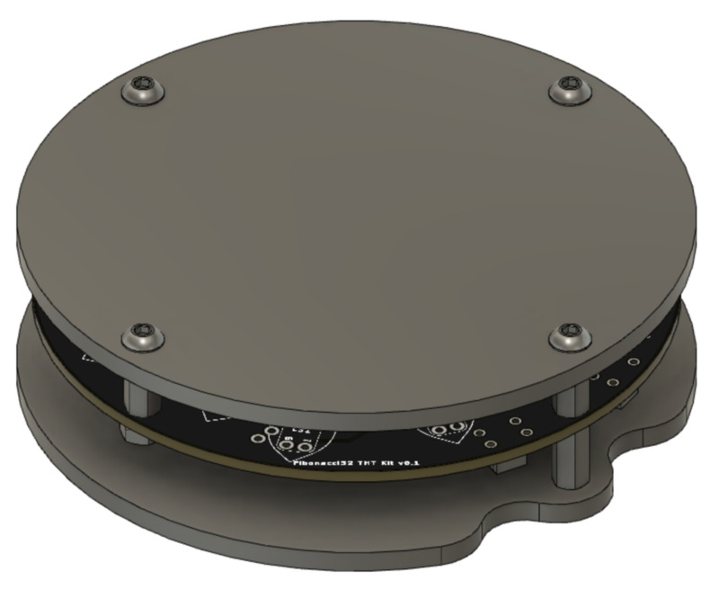
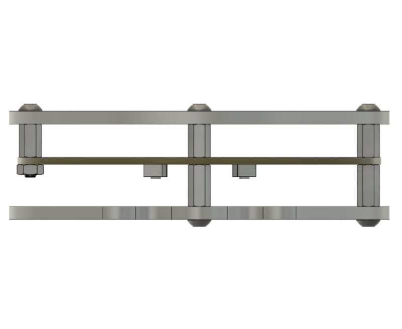
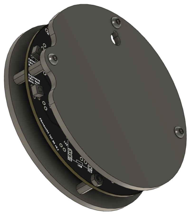
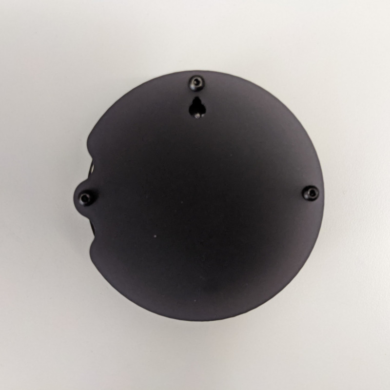
An optional enclosure is also available from Cyber City Circuits.
In disc phyllotaxis, as in the sunflower and daisy, the mesh of spirals occurs in Fibonacci numbers because divergence (angle of succession in a single spiral arrangement) approaches the golden ratio. The shape of the spirals depends on the growth of the elements generated sequentially. In mature-disc phyllotaxis, when all the elements are the same size, the shape of the spirals is that of Fermat spirals—ideally. That is because Fermat's spiral traverses equal annuli in equal turns. The full model proposed by H Vogel in 1979[2] is


where θ is the angle, r is the radius or distance from the center, and n is the index number of the floret and c is a constant scaling factor. The angle 137.508° is the golden angle which is approximated by ratios of Fibonacci numbers.[3]
Fermat's spiral. (2015, October 24). In Wikipedia, The Free Encyclopedia. Retrieved 02:45, February 24, 2016, from https://en.wikipedia.org/w/index.php?title=Fermat%27s_spiral
Open source example firmware: https://github.com/evilgeniuslabs/fibonacci32-demoreel100
~2 hours total
Note: Double-check the position, alignment, and orientation of each component very carefully before soldering!
If you’re new to soldering, I highly recommend reading through a good soldering tutorial, such as the ones by Adafruit and SparkFun.
~30 minutes
The kit may come with header pin sockets. You can use these to make the Nano removable, but if you do, the back of the optional enclosure won’t fit without using taller standoffs.
These instructions do not use the header pin sockets.
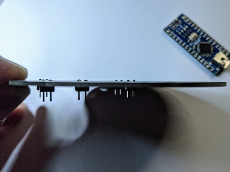
Snap the header pins into sets of two, using side/flush cutters:

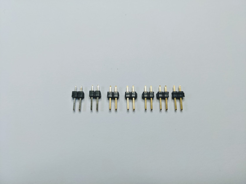
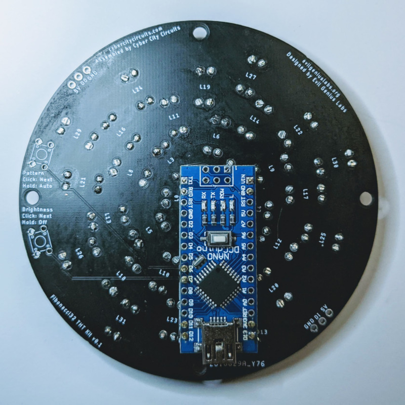
We need five sets right now. Insert the long side of the header pins into the corners and side of the Nano outline, on the back of the PCB.
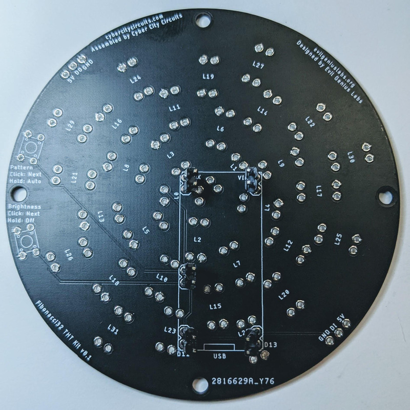
Place the Nano onto the pins, but DO NOT solder the pins on the Nano yet.
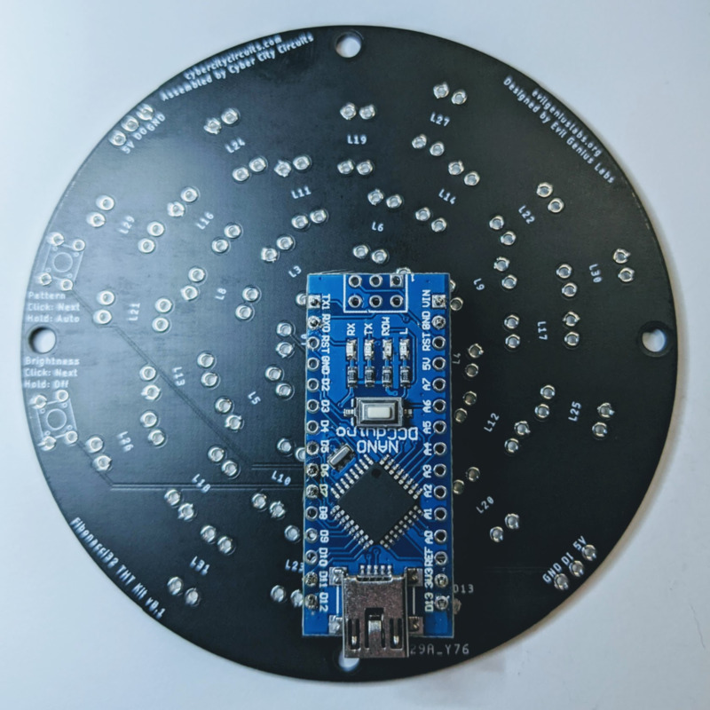
Hold the Nano in place as you flip the whole thing over.
Solder the pins on the front side of the board.

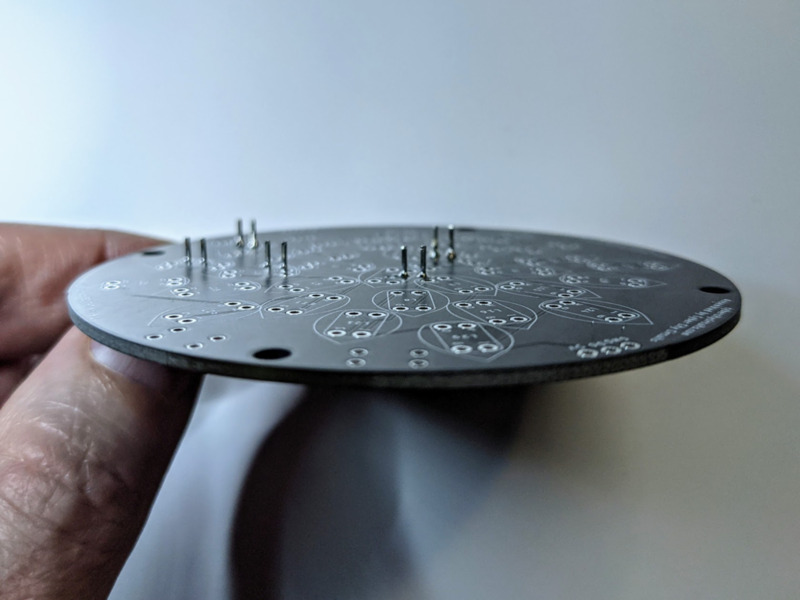
Using side/flush cutters, trim the pins close to the PCB.
Flip the board back over and take the Nano off. Again, DO NOT solder the Nano on just yet.

~30 minutes
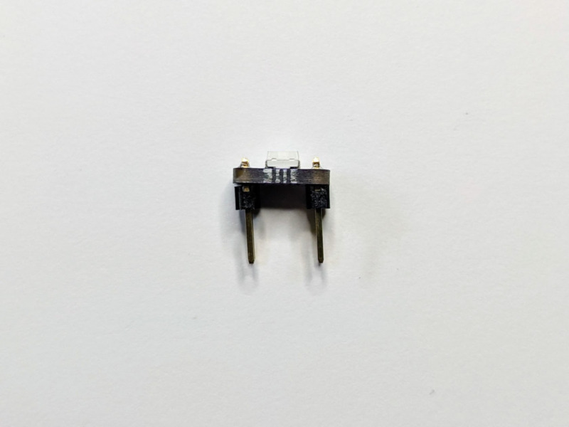
Carefully snap all of the LEDs apart from the panel. You can use needle-nosed pliers to help, but only grip the PCB with them, not the LEDs, which can be damaged easily.
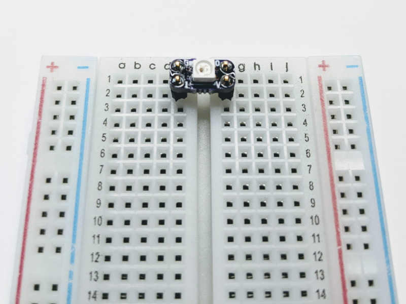
Insert two sets of pins into opposite sides of the gap in a breadboard. If you don’t have a breadboard, you can use the Fibonacci PCB for this instead.

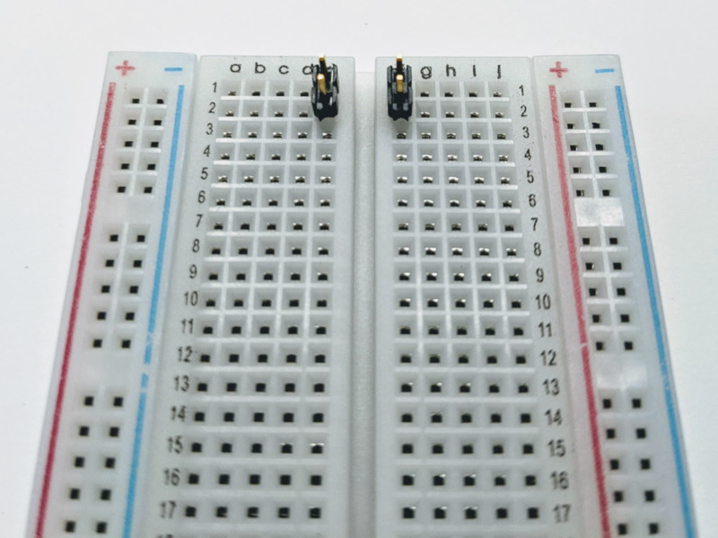
Place an LED PCB onto the pins, and solder them, one at a time, making sure the LED PCB is level.
You may need to hold it level while soldering the first pin.


Remove the LED PCB, and repeat for the rest.
~1 hour
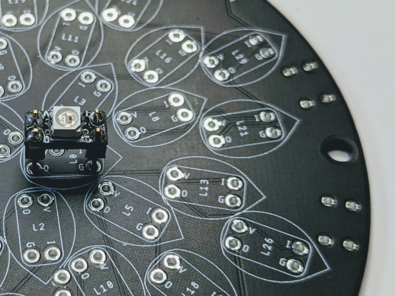
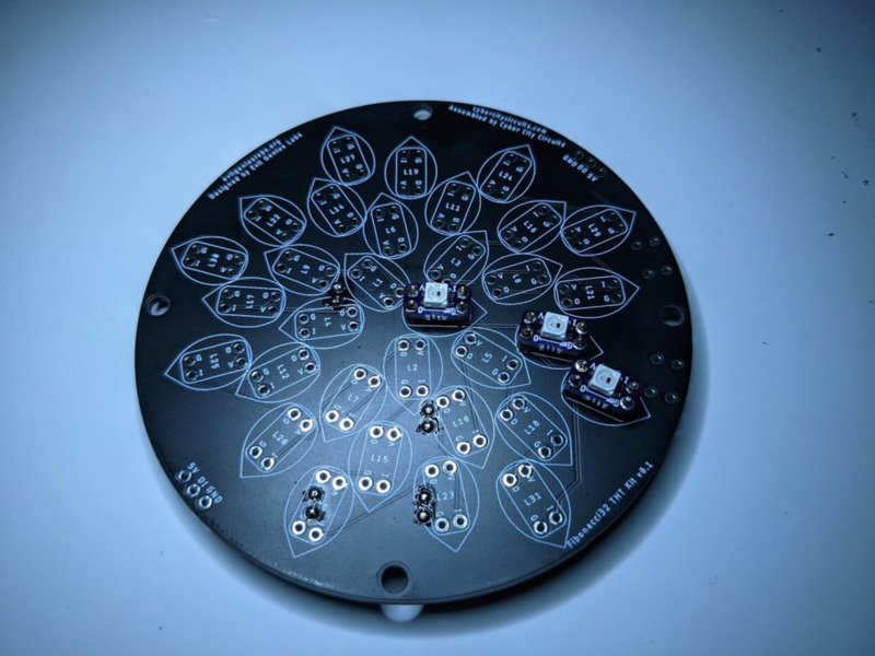
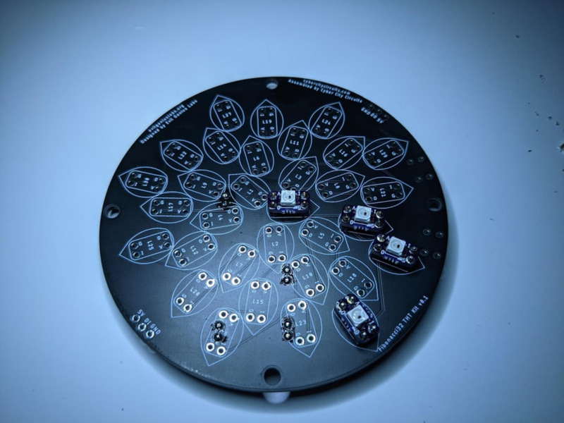
Note: Double-check the orientation of each LED very carefully before soldering! It is much more difficult to desolder and fix incorrectly placed LEDs.
The small black dot in the middle of each and every LED should point toward the outside of the main round PCB.
You can insert and solder the LEDs in any order. If you follow the order listed below, you can stop and test the LEDs at any point. It’s not a bad idea to test after each LED. If a mistake is made, or an LED has failed, it will be easier to fix the fewer LEDs have been assembled.
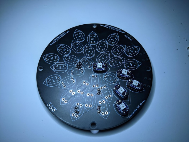
You can test the LEDs by placing the Nano onto the pins, carefully checking you have it aligned correctly, with the USB port toward the edge where noted. Hold it in place while plugging in the USB cable, and the LEDs should light up. If not, make sure the Arduino code has been uploaded (see above).
Double-check and make sure that the small black dot in the middle of the LED points toward the outside of the main round PCB.
21
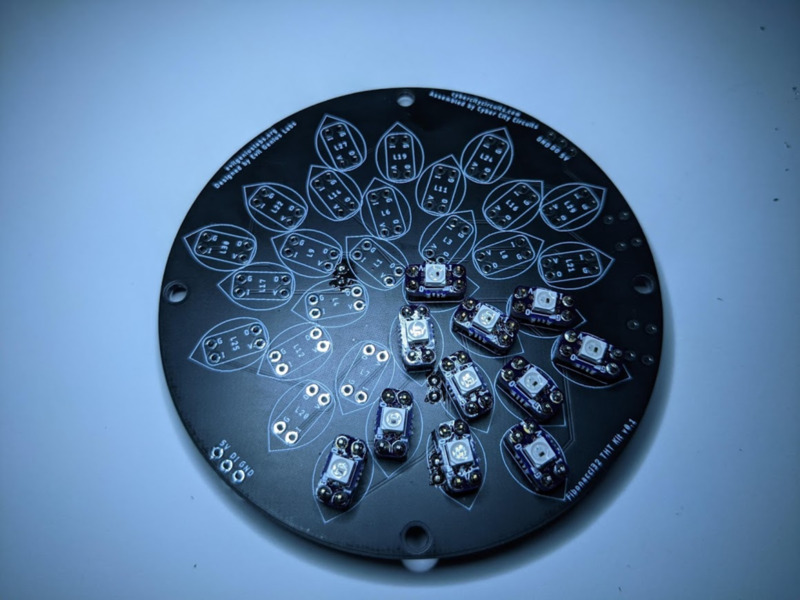
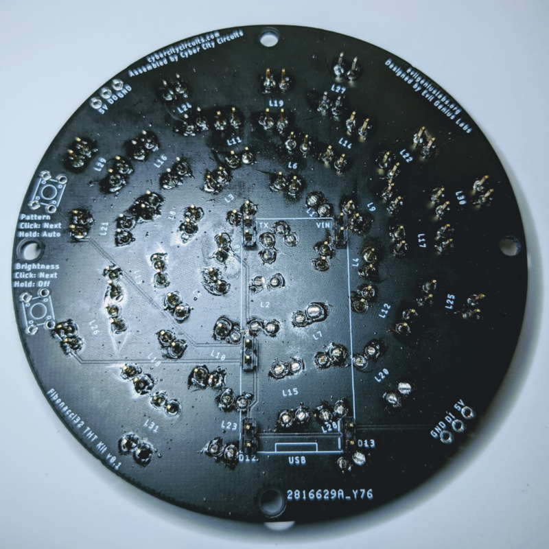
Trim all the LED pins on the back side of the PCB with flush cutters.
Test the LEDs, make sure they all light up.
Again, make sure it’s aligned correctly, with the USB connector towards the edge.
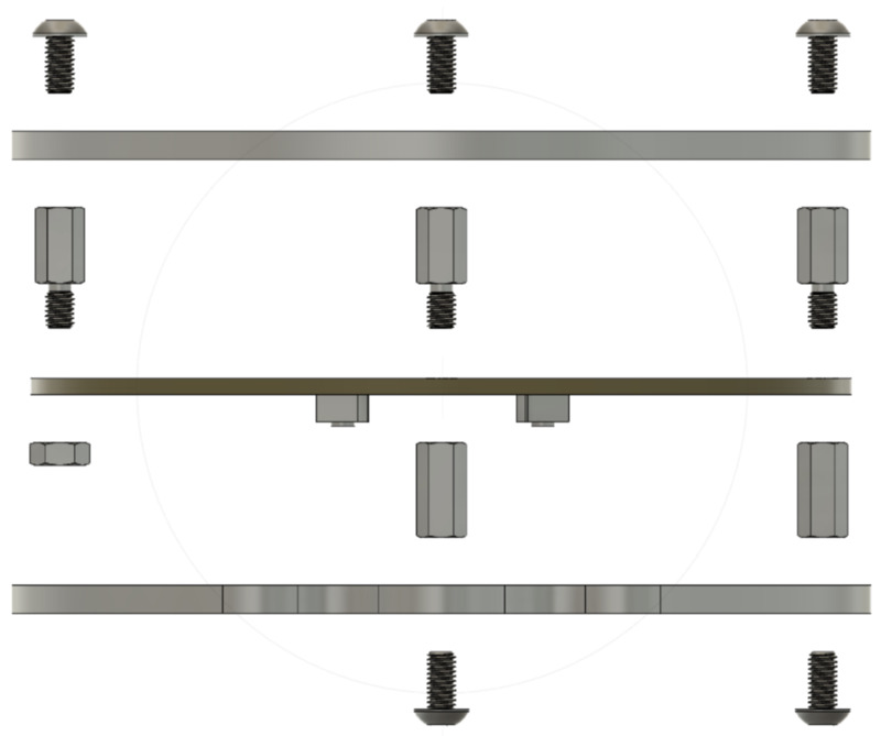
Insert M3x6mm Button Head Hex Screws into the holes in the back plate and hand-tighten.