
Evil Genius Labs
Purveyor of finely hand-crafted pixels. ꩜
Purveyor of finely hand-crafted pixels. ꩜


IcosaLEDron is a 20-sided polyhedron with one WS2812B-Mini-3535 addressable RGB LED per face. Each face is an equilateral triangle printed circuit board. Each edge has five castellated edge holes in a symmetrical arrangement that allows connection at nearly any angle.
The triangles can be assembled into any deltahedron that (obviously) does not have intersecting faces, although routing the data signal may not be possible. Some examples:
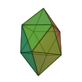 Gyroelongated Square Bipyramid
 Tetrahedron
Augmentation
4 tets + 1 oct
Tetrahedron
Augmentation
4 tets + 1 oct

Deltahedron from Wikipedia, The Free Encyclopedia. https://en.wikipedia.org/wiki/Deltahedron
Parts
Includes only the printed circuit board with LEDs, does not include parts that are required to assemble and run it (microcontroller, power supply, wires, etc).
Parts that are not included, but are required to assemble and use:
Parts I use in my IcosaLEDron builds (also not included):
3D printed parts:
Remixed from the fantastic Snap-together Icosahedron (d20) by aveday_
I 3D printed all parts at high speed, 0.2mm layer height, no brim or raft.
The triangular frame parts can all be printed without supports:
OR
I did have to enable supports, touching build plate only, for the dome covers.
OR
Open source example firmware: https://github.com/jasoncoon/icosaLEDron
Note: Double-check the position, alignment, and orientation of each component very carefully before soldering!
If you’re new to soldering, I highly recommend reading through a good soldering tutorial, such as the ones by Adafruit and SparkFun.
Important! Fire Danger! Make sure you use a multimeter to test for shorts after each new connection, test to make sure newly-connected LEDs work, then turn off the switch and disconnect the USB cable before proceeding!. Testing after each PCB ensures that no bad connections are missed. Disconnecting power before proceeding ensures that a short circuit doesn’t damage any LEDs, components, the Feather board, the LiPo battery, etc. A short can cause damage to the LiPo, which can cause sparks, fire, property damage, bodily harm, etc.
Check the polarity of your LiPo battery and JST extensions before assembling anything! There is unfortunately no standard for polarity on these, apparently. My LiPo battery and JST extensions were wired backwards compared to the Feather board. Thankfully all Feathers, and likely all Adafruit products, do use the same polarity. When looking into the LiPo connector socket on the Feather board, the left pin is positive, the right pin is negative. If the connectors do not match, use a small flat screwdriver or knife to carefully pry the plastic tabs that hold the contact inside the connectors, then gently pull the wires out. Be extremely careful not to touch the exposed battery leads! Push them back in to the correct side.

Follow Adafruit’s excellent instructions to create a power switch for the LiPo battery, but I recommend also adding heat shrink tubing to insulate the exposed switch pins as well!
Connect the LiPo battery, switch assembly, and Feather board. Test the power switch, ensuring it powers the Feather. Connect the Feather with a USB cable to a computer or power adapter, and ensure the battery charging light comes on when the switch is on.
Upload the firmware to the Feather board using Arduino, CircuitPython editor, etc. Ensure the Feather is working correctly before assembling further.
Cut a length of wire long enough to reach from one of the Feather board’s digital output pins (I used D5) to the first LED triangle PCB. Cut it longer than needed, we can trim it down later, or tuck the excess inside.
Strip a few millimeters of insulation off the end of the wire, then solder to the digital output pin.
Repeat for the GND and BAT pins.
Hold two of the 3D printed triangular frame pieces securely, one in each hand. Align the hinges, then snap them together py pressing them together firmly.


Rotate the connected pieces along the hinge pivot, back and forth, several times to loosen the hinges. Separate the pieces by holding them firmly, one in each hand, rotating the hinge outward, then snapping them apart. Repeat for each edge of each piece. Doing this will make assembly and disassembly (if needed) of the frame much easier.
Insert the switch into the 3D printed triangle with the switch holder.


Feed the BAT, GND, and Data wires through the 3D printed triangle with the slot for the Feather’s USB port edge.
Carefully snap the triangle PCBs apart. Hold securely and very closely on both sides of a single perforation and bend to flex and snap the perforation. Do not flex the entire panel at once. Sandpaper can be used to clean up any rough edges, but do this in a well ventilated area with a mask on to prevent breathing in the dust.

Strip and then solder the ends of the wires to the 5V, DI (Data In), and G (Ground) pins on one of the triangle PCBs. Use the set of three holes in the triangle PCB, not the ones on the edge.

Turn the switch on, and/or connect the USB cable, and ensure the LED on the triangle PCB lights up. Do not proceed if it does not. Ensure you’ve uploaded the firmware using Arduino, MicroPython editor, etc.
Take a break. Seriously. Stretch your legs. Drink some water. Go for a walk. :)
Welcome back, let’s proceed.
Align the triangle PCB to the face. The USB connector should be aligned inside the slot in the triangle PCB. Feed the wires inside.


Insert an M3 screw in the hole above the LED, and carefully hand-tighten it with a hex driver. Do not over-tighten. Ensure the edges of the PCB are aligned with the edges of the triangle frame piece.
The two Feather holder pieces go on opposite faces of the icosahedron. The USB port of the Feather should be flush with the face. The other end of the Feather goes in the slots of the opposite face. One side of every triangle has a notch in the hinges, snap this edge on the same side as the Feather holder slots. Be very careful with the fragile antenna on the Feather Sense.


Assemble the IcosaLEDron 3D printed parts, with the Feather board, battery, and wires tucked inside. First, add pieces to connect the top and bottom end Feather holder pieces. Be very careful not to pinch or crimp any wires as you tuck them inside and snap more pieces on.


Start connecting pieces in the remaining spaces.


When you need to snap in a piece with two adjacent pieces, you should be able to set it in the gap, with the hinges aligned, then using your thumb and pointer finger, snap them together, one side at a time.

When you get to the last piece, with an adjacent piece on each of the three sides, follow the same steps. Set it in the gap, with the hinges aligned, then using your thumb and pointer finger, snap them together, one side at a time.


Ensure all pieces are firmly connected, with only minor gaps in the seams.


Turn on the switch, make sure everything still works and lights up.
Take another break. Stretch.

Turn off the switch and disconnect the USB cable. Use a multimeter to ensure there is no voltage or shorts between the BAT and GND pins.
The triangle PCBs each have a small jumper pad used to direct the output direction of the serial LED data signal. We’re going to connect the PCBs in the order and arrangement shown in the picture above.
The signal for the first four PCBs is going to be routed out of the left edge.
“Tin” both the center and left jumper pads, one at a time. Heat the pad with your soldering iron, then melt a small amount of solder onto the pad. Repeat for the other one. Now hold the soldering iron on both pads at once, and melt more solder onto them. The resulting solder blob should connect the two pads. Repeat if necessary. Use flux if the solder is not “sticking” to the pads.
Place the second triangle PCB onto the face to the left of the first PCB, with the DI pad on the second PCB aligned with the DO pin on the first. Secure it in place with M3 screws.
Ensure both triangle PCBs are aligned with the triangle frame pieces they are mounted to. The gap between the PCBs should be straight and even along the entire edge.
Tin the DO pad on one PCB, then the DI pad on the other PCB. Now connect the tinned pads by holding the soldering iron between the pads, touching both pads at the same time. Melt just enough solder into the gap to connect the pads.
Repeat this process on one set of GND and 5V pads. To reduce the risk of short circuit connections, you can just connect the G pads on one side, and 5V pads on the other side of the edge, so that they’re not adjacent.
Use a multimeter to ensure there are no shorts between 5V, GND, and the data pins. If there are, rework the connections. Repeat.
Turn on the switch, and/or connect the USB cable. Ensure the second LED lights up. Do not proceed if it does not. Check the solder connections.
Turn off the switch and disconnect the USB cable!
Repeat the above steps for the next three PCBs, testing and then disconnecting power after each. Use M3 screws to keep each one in place as you solder.
Take another break. Marvel at your soldering and assembly skills, patience, and awesomeness.
You should now have the top cap of the icosaLEDron assembled!
The LED data signal output is going to turn right on the fifth PCB. So connect the center and right jumper pads with solder, following the same steps as before.
Assemble the following 10 triangle PCBs in the same way, following the order shown in the picture above, along the center of the icosahedron. Make sure you test for shorts after each new PCB, test to make sure newly-connected LED works, then turn off the switch and disconnect the USB cable before proceeding!
You should now have the top and center row of the icosaLEDron assembled. Repeat the above steps to complete the bottom cap of five PCBs. Remember to test after each PCB, then disconnect power.
Turn it on. Hold it in your hand. Marvel at its beauty.
 Tetrahedron
 Octahedron