
Evil Genius Labs
Purveyor of finely hand-crafted pixels. ꩜
Purveyor of finely hand-crafted pixels. ꩜

Retired
See Fibonacci256 HDR Pixelblaze and Fibonacci256 Expanding Pixelblaze instead.
Fibonacci256 is a beautiful 166mm circular disc with 256 RGB LEDs surface mounted in a Fibonacci distribution. Swirling and pulsing like a colorful galaxy, it’s mesmerizing to watch.
It consists of 256 WS2812B-Mini 3535 RGB LEDs, arranged into a circular Fermat’s spiral pattern.
I have created several LED art pieces in Fibonacci patterns. They are all very labor intensive to create, and so are fairly expensive and limited in quantity. I wanted to come up with a Fibonacci layout that was at least slightly easier to create, and therefore more affordable.
I have RGB LEDs in just about every form they come: strips, strings, rings, discs, etc. The LEDs on most discs are arranged in very regular rings. Fibonacci256 is different. The LEDs are arranged in a Fibonacci distribution. The makes the layout very organic and seemingly messy. But with the proper animation, spiral patterns emerge with spectacular results.
Each of the 256 WS2812B-Mini 3535 RGB LEDs has its own decoupling capacitor built in. The top and bottom of the PCB are large 5V and GND planes, to allow for the large amount of current required by the 256 LEDs. The max theoretical frame rate is ~130 FPS.
In disc phyllotaxis, as in the sunflower and daisy, the mesh of spirals occurs in Fibonacci numbers because divergence (angle of succession in a single spiral arrangement) approaches the golden ratio. The shape of the spirals depends on the growth of the elements generated sequentially. In mature-disc phyllotaxis, when all the elements are the same size, the shape of the spirals is that of Fermat spirals—ideally. That is because Fermat's spiral traverses equal annuli in equal turns. The full model proposed by H Vogel in 1979[2] is


where θ is the angle, r is the radius or distance from the center, and n is the index number of the floret and c is a constant scaling factor. The angle 137.508° is the golden angle which is approximated by ratios of Fibonacci numbers.[3]
Fermat's spiral. (2015, October 24). In Wikipedia, The Free Encyclopedia. Retrieved 02:45, February 24, 2016, from https://en.wikipedia.org/w/index.php?title=Fermat%27s_spiral
Your Fibonacci256 should automatically play a playlist of pre-selected patterns endlessly.
For more control, you can connect to it via wi-fi.
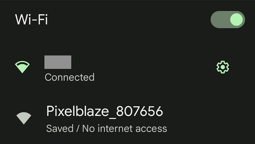
If not already connected to a wi-fi network, your Fibonacci256 will create its own network named Pixelblaze_XXXXXXX, where XXXXX is a code unique to your Fibonacci256. You should see it in the list of wi-fi networks available on a computer or mobile device:
Note: If you can’t find the Fibonacci256’s wi-fi network, it may not be in setup mode.
To put it in to setup mode:
You should see a pop-up and/or automatically get redirected to configure the Fibonacci256’s wi-fi settings. If not, open a browser and go to http://192.168.4.1
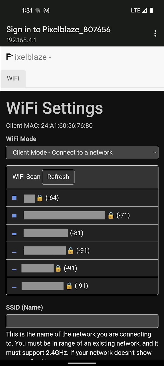
In WiFi Settings you an configure your Fibonacci256 to run in one of two modes:
In this mode your Fibonacci256 can connect to an existing wi-fi network. Use this mode while at home or another location with an existing wi-fi network that you can connect to.
Choose the wi-fi network to which you’d like to connect, or enter the SSID (Name) if you know it, it’s hidden, etc.
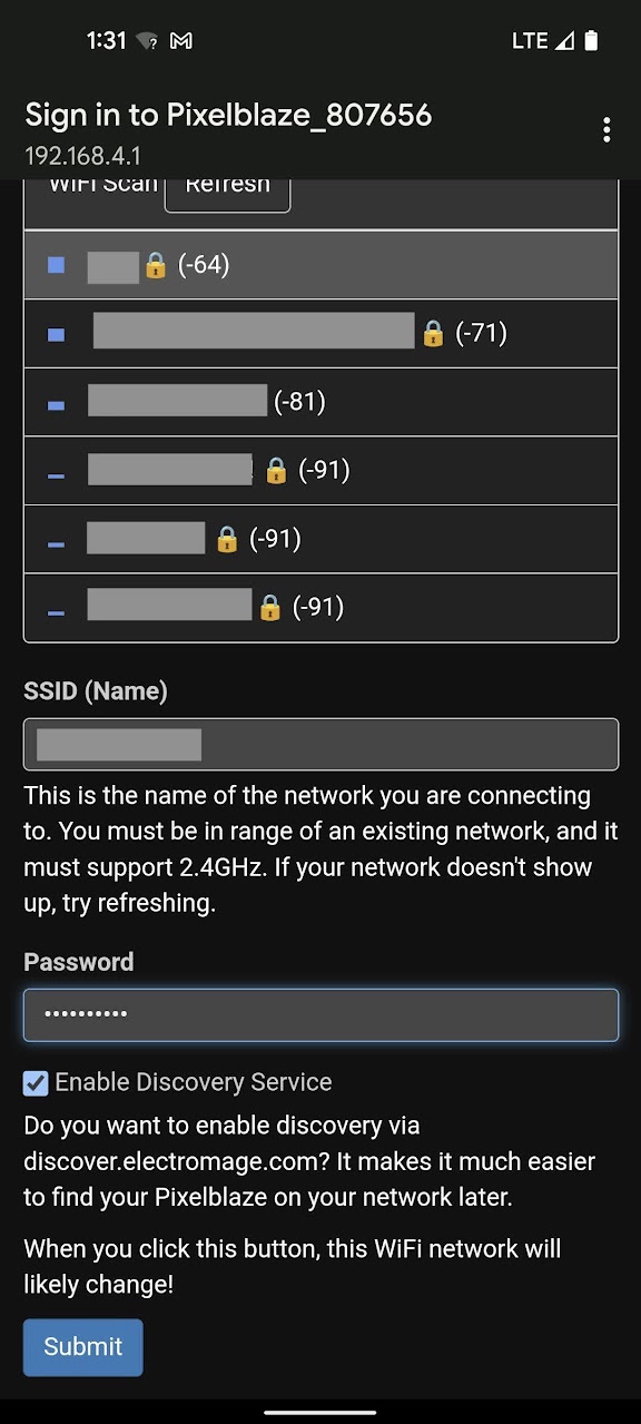
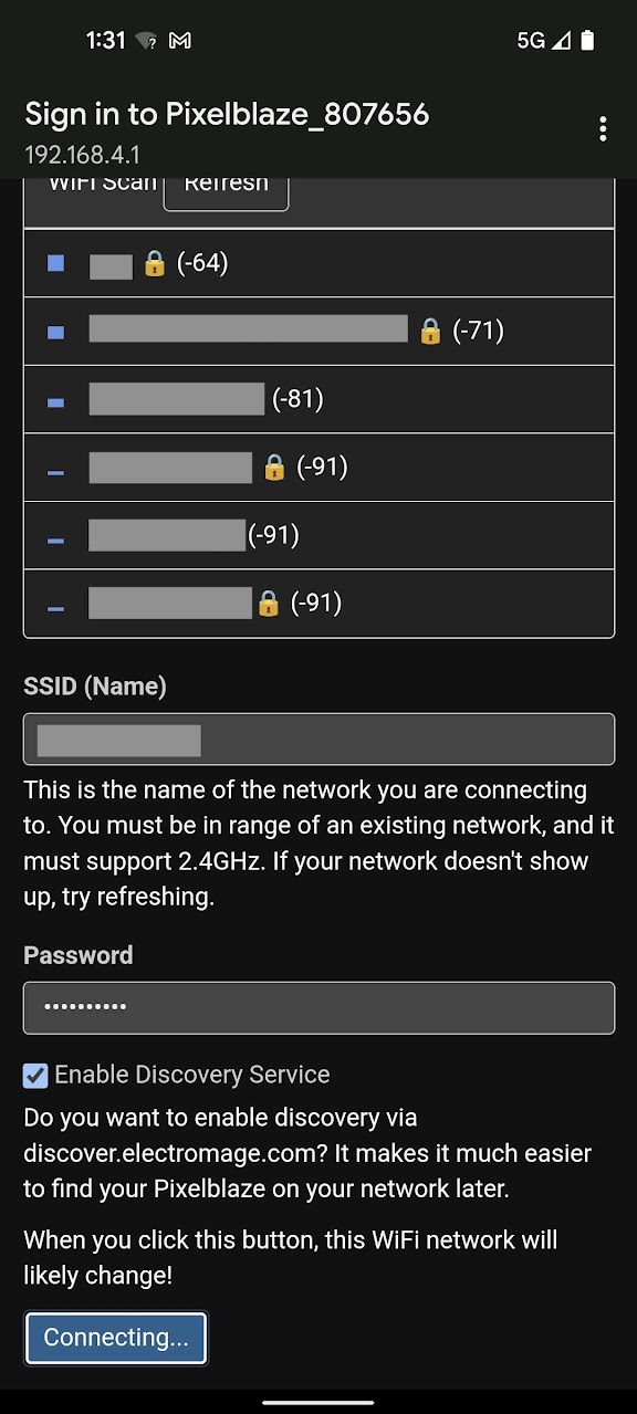
Click Submit to connect.
In this mode your Fibonacci256 will create its own wi-fi network that you can connect to from another device. Use this mode when outdoors or away from other wi-fi networks.
If you’ve already chosen Client Mode and followed the instructions above, skip down to Next Steps
Congratulations! You should now be able to connect to and configure your Fibonacci256!
After you’ve gotten your Fibonacci256 connected to a wi-fi network, there are a few settings you should check and be aware of.
Open your Fibonacci256’s web app and click on the Settings tab.
We won’t go over every setting on this page, just the ones that are important for the use of your Fibonacci256.
These settings should always be set to the following values to match the type and quantity of LEDs in your Fibonacci256:
You shouldn’t need to change anything on the Mapper tab. This page just contains the pixel map, which is the location of each of your Fibonacci256’s LEDs. It’s used by the Pixelblaze controller in patterns.
If you ever do need to reset to the Fibonacci256’s default map, use these values:
[[164.7,158.81],[198.91,162.03],[214.26,167.86],[225.23,175.33],[233.45,184.02],[239.48,193.67],[243.6,204.05],[245.94,214.95],[246.59,226.2],[245.62,237.61],[243.07,249.05],[239.01,260.31],[233.48,271.27],[226.56,281.77],[218.29,291.68],[208.78,300.85],[188.78,303.02],[199.16,295.16],[208.38,286.41],[216.33,276.91],[222.93,266.78],[228.1,256.17],[231.75,245.21],[233.81,234.06],[234.19,222.89],[232.77,211.84],[229.41,201.09],[223.87,190.8],[215.69,181.16],[203.78,172.31],[183.85,164.05],[191.06,173.16],[204.98,184.3],[213.4,195.19],[218.55,206.24],[221.21,217.4],[221.76,228.57],[220.43,239.63],[217.36,250.44],[212.68,260.85],[206.52,270.73],[198.97,279.94],[190.15,288.37],[180.15,295.89],[169.1,302.39],[157.12,307.78],[137.75,302.95],[150.1,299.07],[161.65,293.96],[172.28,287.71],[181.83,280.42],[190.19,272.17],[197.23,263.09],[202.82,253.28],[206.82,242.86],[209.06,231.93],[209.32,220.61],[207.29,208.94],[202.39,196.89],[193.28,184.07],[173.15,167.18],[180.26,178.98],[191.22,195.48],[196.04,209.03],[197.5,221.4],[196.47,232.94],[193.38,243.74],[188.52,253.77],[182.1,262.94],[174.29,271.19],[165.24,278.43],[155.11,284.57],[144.04,289.52],[132.17,293.23],[119.65,295.62],[106.61,296.64],[77.2,283.57],[90.25,285.51],[103.1,286.01],[115.62,285.09],[127.65,282.77],[139.04,279.11],[149.61,274.14],[159.21,267.92],[167.69,260.52],[174.85,251.99],[180.51,242.35],[184.41,231.63],[186.19,219.72],[185.26,206.31],[180.18,190.19],[169.13,178.32],[175.41,200.38],[175.84,215.53],[173.29,228.05],[168.59,238.8],[162.17,248.08],[154.33,255.99],[145.28,262.55],[135.22,267.74],[124.34,271.55],[112.81,273.95],[100.78,274.92],[88.43,274.43],[75.9,272.47],[63.36,269.06],[40.38,246.9],[51.94,253.09],[63.81,257.86],[75.84,261.18],[87.88,263.01],[99.76,263.35],[111.33,262.19],[122.39,259.5],[132.8,255.31],[142.35,249.57],[150.83,242.25],[158.01,233.25],[163.56,222.29],[166.96,208.73],[167.07,190.25],[160.92,169.28],[160.2,198.97],[155.66,214.45],[149.14,225.88],[141.17,234.73],[132.06,241.52],[122.06,246.47],[111.38,249.7],[100.22,251.3],[88.75,251.29],[77.14,249.72],[65.55,246.63],[54.13,242.04],[43.06,236.03],[32.47,228.64],[18.57,200.19],[27.31,209.86],[36.83,218.3],[46.99,225.42],[57.66,231.14],[68.68,235.39],[79.92,238.11],[91.21,239.23],[102.39,238.68],[113.29,236.35],[123.71,232.13],[133.49,225.8],[142.39,216.94],[150.18,204.53],[156.64,184.76],[147.99,192.2],[138.19,206.62],[128.09,215.78],[117.55,221.76],[106.66,225.32],[95.58,226.78],[84.44,226.36],[73.41,224.21],[62.64,220.42],[52.26,215.11],[42.42,208.35],[33.26,200.27],[24.9,190.94],[17.46,180.47],[11.05,168.98],[14.16,149.23],[19.1,161.23],[25.19,172.31],[32.33,182.37],[40.42,191.27],[49.36,198.92],[59.01,205.17],[69.27,209.93],[79.99,213.05],[91.05,214.38],[102.35,213.73],[113.77,210.78],[125.31,204.98],[137.19,195.05],[151.61,174.96],[140.72,181.92],[125.56,193.76],[112.58,199.57],[100.44,202],[88.88,201.89],[77.88,199.7],[67.49,195.69],[57.8,190.06],[48.92,182.96],[40.93,174.53],[33.95,164.95],[28.06,154.32],[23.34,142.8],[19.88,130.51],[17.74,117.6],[28.22,87.09],[27.41,100.27],[28.01,113.14],[30.01,125.57],[33.34,137.37],[37.97,148.41],[43.82,158.53],[50.83,167.59],[58.92,175.43],[68.03,181.87],[78.08,186.71],[89.07,189.72],[101.03,190.54],[114.21,188.57],[129.58,182.37],[139.67,170.59],[119.04,178.22],[104.18,179.81],[91.59,178.28],[80.53,174.47],[70.77,168.84],[62.24,161.67],[54.95,153.19],[48.93,143.59],[44.21,133.06],[40.83,121.75],[38.85,109.84],[38.28,97.47],[39.15,84.81],[41.47,72.01],[61.6,47.13],[56.41,59.19],[52.67,71.44],[50.4,83.73],[49.58,95.91],[50.26,107.79],[52.4,119.23],[56.01,130.05],[61.07,140.07],[67.57,149.12],[75.55,156.96],[85.09,163.37],[96.39,168],[110.03,170.31],[128.02,169.01],[146.12,161.27],[118.93,162.62],[103.41,159.36],[91.59,153.81],[82.17,146.6],[74.68,138.09],[68.92,128.53],[64.81,118.16],[62.29,107.15],[61.33,95.71],[61.91,83.99],[64.01,72.16],[67.6,60.39],[72.65,48.83],[79.12,37.62],[106.31,21.26],[97.41,30.81],[89.81,41.03],[83.58,51.78],[78.78,62.91],[75.46,74.28],[73.69,85.72],[73.53,97.08],[75.02,108.18],[78.23,118.84],[83.28,128.88],[90.36,138.08],[99.85,146.2],[112.67,152.91],[132.22,157.66],[124.5,149.45],[109.68,140.99],[99.85,131.73],[93.07,121.75],[88.66,111.2],[86.29,100.28],[85.78,89.15],[87.02,77.97],[89.88,66.9],[94.3,56.1],[100.19,45.71],[107.48,35.88],[116.09,26.73],[125.89,18.41],[136.81,11.03],[156.78,12.39],[145.25,18.35],[134.71,25.37],[125.29,33.36],[117.09,42.19],[110.22,51.76],[104.78,61.92],[100.9,72.54],[98.68,83.49],[98.27,94.63],[99.84,105.81],[103.68,116.92],[110.32,127.89],[121,138.79],[141.06,150.99],[134.12,140.8],[121.48,126.99],[114.75,114.65],[111.38,102.8],[110.55,91.3],[111.83,80.17],[114.98,69.48],[119.79,59.35],[126.12,49.89],[133.84,41.21],[142.81,33.43],[152.92,26.65],[164.02,20.96],[175.98,16.45],[188.68,13.2],[220.05,21],[206.81,21.31],[194.02,23.03],[181.8,26.08],[170.32,30.42],[159.7,35.98],[150.09,42.68],[141.64,50.43],[134.5,59.16],[128.84,68.76],[124.84,79.18],[122.74,90.35],[122.88,102.29],[125.86,115.16],[133.11,129.74],[154,153.31],[145.44,138.1],[136.6,118.87],[133.88,104.38],[134.41,91.79],[137.3,80.49],[142.12,70.31],[148.56,61.23],[156.4,53.25],[165.46,46.44],[175.57,40.84],[186.58,36.52],[198.29,33.52],[210.59,31.9],[223.29,31.68],[236.26,32.9],[262.86,50.81],[250.38,46.68],[237.82,43.99],[225.36,42.77],[213.15,43.01],[201.36,44.69],[190.13,47.8],[179.64,52.3],[170.06,58.18],[161.59,65.41],[154.42,74],[148.82,84],[145.13,95.58],[143.92,109.23],[146.54,126.66],[155.6,142.44],[152.43,117.19],[154.43,101.71],[158.99,89.58],[165.4,79.65],[173.26,71.51],[182.3,64.99],[192.3,60.02],[203.06,56.59],[214.41,54.67],[226.15,54.25],[238.13,55.34],[250.18,57.92],[262.15,61.96],[273.89,67.45],[292.6,93.17],[282.3,85.12],[271.46,78.41],[260.19,73.09],[248.67,69.26],[237.05,66.92],[225.49,66.13],[214.15,66.92],[203.2,69.32],[192.84,73.41],[183.26,79.26],[174.69,87.03],[167.39,97.08],[161.77,110.23],[158.64,129.49],[166.42,121.46],[173.56,106.33],[181.94,95.89],[191.31,88.37],[201.43,83.13],[212.11,79.88],[223.17,78.45],[234.43,78.74],[245.71,80.67],[256.87,84.17],[267.73,89.16],[278.16,95.59],[288.02,103.38],[297.16,112.45],[305.47,122.72],[305.88,142.77],[298.94,131.78],[291.03,121.87],[282.26,113.15],[272.74,105.71],[262.61,99.67],[252.02,95.11],[241.1,92.13],[229.99,90.83],[218.86,91.33],[207.86,93.8],[197.13,98.51],[186.8,105.95],[176.91,117.28],[166.75,137.3],[176.36,130.26],[188.83,116.94],[200.48,109.33],[211.95,105.05],[223.32,103.3],[234.51,103.67],[245.42,105.91],[255.93,109.87],[265.9,115.39],[275.21,122.36],[283.74,130.65],[291.37,140.15],[297.99,150.73],[303.52,162.3],[307.85,174.68],[301.35,193.5],[298.55,180.88],[294.45,168.96],[289.14,157.86],[282.69,147.74],[275.19,138.71],[266.75,130.94],[257.45,124.55],[247.4,119.71],[236.69,116.58],[225.41,115.39],[213.57,116.48],[201.07,120.44],[187.35,128.66],[167.57,148.94],[180.65,141.41],[198.51,131.46],[212.56,127.66],[225.08,127.19],[236.54,129.16],[247.06,133.12],[256.65,138.79],[265.25,145.95],[272.81,154.41],[279.25,164.03],[284.5,174.63],[288.49,186.06],[291.16,198.2],[292.46,210.86],[292.37,223.91],[276.82,252.01],[279.87,239.2],[281.46,226.45],[281.61,213.92],[280.33,201.76],[277.65,190.13],[273.6,179.19],[268.22,169.09],[261.56,160.04],[253.65,152.19],[244.51,145.76],[234.11,141],[222.33,138.26],[208.76,138.12],[191.96,142.01],[178.2,152.16],[201.79,147.36],[217.15,148.13],[229.51,151.69],[239.88,157.25],[248.63,164.42],[255.86,172.9],[261.64,182.45],[265.97,192.9],[268.85,204.04],[270.26,215.72],[270.19,227.78],[268.65,240.03],[265.64,252.32],[261.17,264.49],[237.13,285.42],[244.3,274.45],[250.06,263.04],[254.38,251.36],[257.23,239.54],[258.57,227.75],[258.39,216.14],[256.65,204.89],[253.33,194.18],[248.41,184.2],[241.8,175.13],[233.38,167.23],[222.85,160.8],[209.45,156.28],[190.54,154.7]]
Fibonacci256 comes with a wide variety of patterns built-in. By default, it will automatically play a playlist of pre-selected patterns.
The sequencer can be configured via the web interface over wi-fi in the following ways:
Parts:
Instructions:
Pixelblaze output:
Pixelblaze expansion pins:
Pixelblaze Sensor Expansion Board:
Acrylic back and standoffs:
Mount the Pixelblaze and Sensor Expansion assembly
DC input board:
Ensure all screws are hand tightened, including the ones on the matte side of the acrylic back.
Cables:
Secure the new back panel in place using the screws you set aside earlier, after removing the old back cover.