
Evil Genius Labs
Purveyor of finely hand-crafted pixels. ꩜

Purveyor of finely hand-crafted pixels. ꩜
6x6x6 Addressable RGB LED Cube
This is a new design, based on the original 6x6x6 cube which is no longer available to buy by Looking Glass (formerly L3D): https://github.com/Looking-Glass/L3D-CUBE-6X6X6Cube-Coding
It consists of 216 5mm WS2812 addressable RGB LEDs, divided into 36 vertical sticks, each with 6 LEDs. Each stick has a 2x2 right-angle pin header (5V, GND, Data In, and Data Out). The data is routed from the Data In pin to the first (bottom) LED, which has its Data Out pin connected to the Data In pin of the next LED, etc. The last (top) LED on the stick then has its Data Out pin routed back down the stick to the Data Out pin on the header.
Quantity 36 of 2.54mm 2 x 2-pin Female Double Row Straight Header Sockets are included.
In case extras are needed they can be purchased here: https://amzn.to/4ayFVd5
Note: You can download and 3D print the base connector soldering jig which makes the process much easier.
Do not solder the power jack connector until all of the sockets are soldered onto the base!
Make sure the 2x2 header sockets are placed on the side with the square markings!
Insert one row of the 2x2 header sockets into the base PCB, on the side with the square markings.
Carefully and gently place the jig onto the PCB, over the header sockets. If any fall out, remove the jig and replace them into the PCB.
Make sure all of the pins come through the holes in the base without getting bent. Make sure the tabs on the jig are inserted into the slots on the base PCB.
Flip the jig and base PCB over and solder just one pin on each socket, making sure the PCB remains flat and flush against the jig throughout.
Flip it back over, remove the jig, and ensure the header sockets are flat and flush against the PCB, and that they are straight and aligned with the square markings on the base PCB.
If any are not straight, hold the socket with one hand while reheating the solder on the other. Hold it aligned in place while removing the soldering iron until the joint cools. Repeat for any other sockets that are not straight and flush.
Place the jig back on, flip it over, and solder the remaining pins for this row.
Repeat the above steps for each row of headers.
Insert just one socket pin-first into the PCB at a time (the side with the square white outlines).
Hold the socket while turning the base over and soldering one pin.
Turn it back over and make sure the socket is straight, lined up with the white square outline.
If it’s not straight, hold the socket with one hand while reheating the solder on the other. Hold it aligned in place while removing the soldering iron until the joint cools.
Repeat the above steps fore each of the header sockets.
Either way, you can now solder the power jack connector and JST-XH 3-Pin connector (if desired) onto the base.
The power jack connector goes on the top of the base, the same side as the sockets.
The JST-XH 3-Pin connector goes on the bottom of the base, the opposite side as the sockets, on the “DIN” pins.
Your LED strips may come all connected in one PCB piece. If so, you’ll need to carefully and gently separate them along the scored lines.
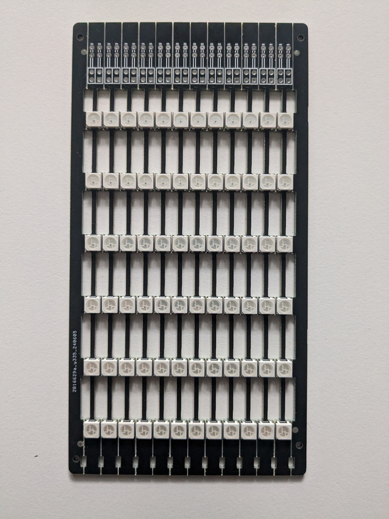
I use a pair of needle-nose pliers with sections of heat-shrink tubing over the ends to protect the PCBs. Grip on one side of the score line with your fingers and the other with the padded pliers.
Very gently and carefully, repeatedly flex the PCB downwards (away from the LED side). Repeat this on the opposite end of the same strip.
Repeat this until the strip starts to separate. Repeat on each strip until all 36 are separated.
36 of the 2.54mm 2 x 20-pin Male Double Row Right Angle Header Strip are included.
In case extras are needed they can be purchased here: https://amzn.to/4e0p4Rp.
These can be difficult to cut into sections of two (2 x 2) pins. I use thin, sharp side flush cutters, and “sacrifice” one row in between each, but your results may vary.
Alternatively, you can find them already cut into 2x2 sections for a little more: https://www.digikey.com/en/products/detail/adam-tech/PH2RA-04-UA/9830448
Insert one 2x2 section of the right angle header pins into each of the strip PCBs, on the side with the square white outlines.
Insert one 2x2 section of the right angle header pins into each of the strip PCBs, on the side with the square white outlines.
Make sure the pins are fully inserted all the way through the strip PCBs.
Flip the strip over and solder only one pin. Flip it back over and make sure the pins are straight (aligned with the strip) and fully-inserted. If not, heat one pin with the soldering iron while carefully (the pins will get HOT!) align and insert, holding while removing the soldering iron and allowing the joint to cool. Solder the other pins on this strip.
Before repeating the above steps for the rest of the strips, it’s a good idea to test them as you go.
Connect your LED controller. I use and highly recommend the brilliant PixelBlaze by ElectroMage. Connect 5V, Data In, and GND. Run a test pattern. Insert one stick into the socket nearest the Data In (DIN) pin and make sure it fully lights up.
Repeat the above steps to solder the pins and test the strip.
Pixelblaze output:
Pixelblaze expansion pins:
Pixelblaze Sensor Expansion Board:
Your parts may look slightly different than the pictures below. For example, if you didn’t order the PixelBlaze controller.
Lay the back and one of the frosted acrylic side pieces side-by-side as shown. Please carefully note the orientation and layout of the parts:
Insert the tabs of one piece into the slots on the other:
Repeat for the other side pieces:
Carefully flip the whole assembly over so the “feet” are pointint up:
Insert four of the corner pieces into the slots closest to the “feet”:
Very carefully flip the LED cube assembly over. Make sure the corner pieces stay in place. Align the power connector (if present) on the base PCB with the hole in the back panel (if present) and insert the LED cube assembly into the enclosure. The base PCB should come to rest flat on top of the corner piece tabs inside the enclosure:
Insert four of the M3 x 15 + 6mm standoffs into the corner holes of the PCB. Very loosely hand-tighten them using a 5mm nut driver. We will tighten them later after the entire enclosure is assembled:
Very carefully flip the whole assembly over and insert the remaining four corner pieces into the slots:
Place the clear acrylic top frame onto the corner piece tabs:
Place the clear acrylic LED guide piece with the holes and slots on top of the rail. Make sure the tops of the LED sticks are roughly aligned with the slots. Don’t worry if they don’t align perfectly yet, we’ll adjust them later:
Place one of the clear acrylic LED guide pieces with slots on top of the rail, in between the rows of LEDs:
Place another of the clear acrylic LED guide pieces with slots on top of the rail, in between the rows of LEDs:
Slide the guide towards the LEDs, and adjust the top tips of the LED sticks into the slots as you go:
Continue placing each of the clear acrylic LED guide pieces with slots on top of the rail, in between the rows of LEDs, and adjusting the tops of the LED sticks into the slots:
Double-check and make sure each of the tips of LED sticks is held inside one of the slots, adjusting as needed:
Place the frosted acrylic top panel on top:
Insert four M3 x 12mm screws into the corner holes. Make sure they go through the top panel, LED guides, and top rail, and into the holes in the corner pieces. Make sure each of the corner pieces is fully inserted. Loosely hand tighten them:
Lightly hand tighten the screws on top and the standoffs on the bottom. DO NOT over-tighten them, as this can crack the acrylic corner pieces. It is not important for them to be tight, just enough to hold the enclosure together. It does not matter if any of the screws won’t fully tighten, as long as they stay in place:
If you purchased the PixelBlaze controller, your kit will come with a bottom mount panel. Align the parts as shown here:
Attach the M2 standoffs to the PixelBlaze using the short M2 screws:
Align the standoffs with the holes in the bottom plate and attach using the slightly longer M2 screws:
Flip the LED cube over and connect the cable between the PixelBlaze and the base PCB. The cable can only be inserted one way. The base PCB side has three connectors, the PixelBlaze has four:
Flip the bottom panel over. Turn it a few times to wind the cable up a bit. Place the bottom panel on the bottom of the cube, aligning the holes in the back panel with the USB port and line in jack on the PixelBlaze:
Ensure the wires are not pinched and do not block the PixelBlaze button inside the hole in the bottom panel:
Attach the bottom panel to the cube with the short M3 screws:
Your cube should automatically light up. Press the button to change to a different pattern.
For more control, you can connect to it via wi-fi.
If not already connected to a wi-fi network, your PixelBlaze will create its own network named Pixelblaze_XXXXXXX, where XXXXX is a code unique to your PixelBlaze. You should see it in the list of wi-fi networks available on a computer or mobile device:
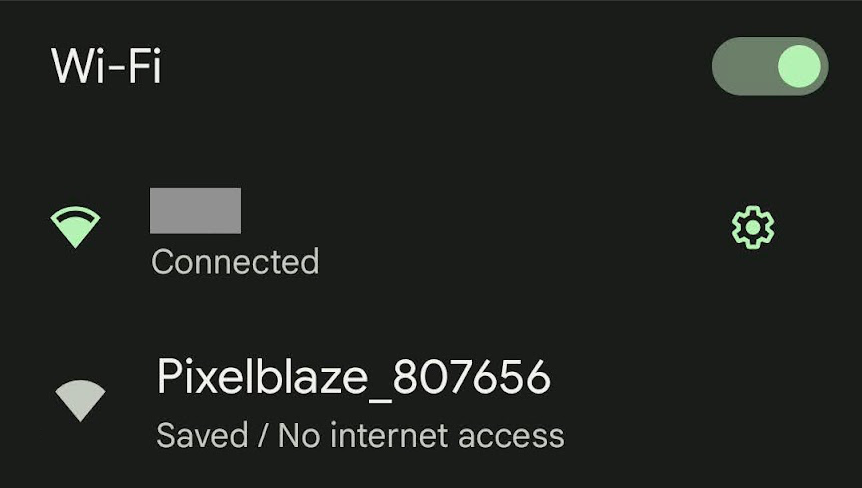
Note: If you can’t find the PixelBlaze’s wi-fi network, it may not be in setup mode.
To put it in to setup mode:
You should see a pop-up and/or automatically get redirected to configure the PixelBlaze’s wi-fi settings. If not, open a browser and go to http://192.168.4.1
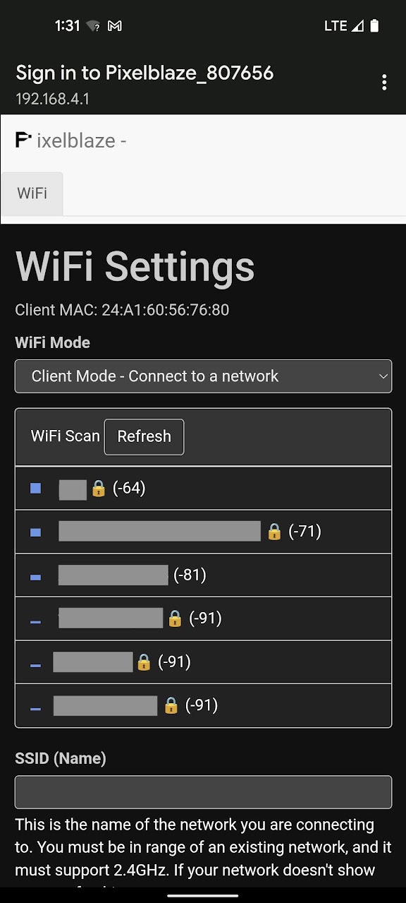
In WiFi Settings you an configure your PixelBlaze to run in one of two modes:
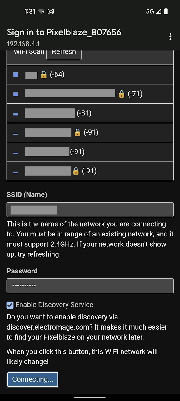
In this mode your PixelBlaze can connect to an existing wi-fi network. Use this mode while at home or another location with an existing wi-fi network that you can connect to.
Choose the wi-fi network to which you’d like to connect, or enter the SSID (Name) if you know it, it’s hidden, etc.
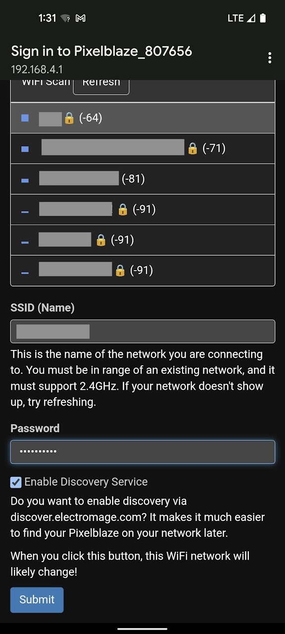
Click Submit to connect.
In this mode your PixelBlaze will create its own wi-fi network that you can connect to from another device. Use this mode when outdoors or away from other wi-fi networks.
If you’ve already chosen Client Mode and followed the instructions above, skip down to Next Steps
Congratulations! You should now be able to connect to and configure your PixelBlaze!
You can download this backup file LED Cube 6x6x6.pbb and restore it with the Restore from Backup button at the bottom of the PixelBlaze web UI’s Settings tab/page.
Alternatively, here are the important PixelBlaze settings:
[
  [0, 0, 0], [0, 0, 1], [0, 0, 2], [0, 0, 3], [0, 0, 4], [0, 0, 5],
  [1, 0, 0], [1, 0, 1], [1, 0, 2], [1, 0, 3], [1, 0, 4], [1, 0, 5],
  [2, 0, 0], [2, 0, 1], [2, 0, 2], [2, 0, 3], [2, 0, 4], [2, 0, 5],
  [3, 0, 0], [3, 0, 1], [3, 0, 2], [3, 0, 3], [3, 0, 4], [3, 0, 5],
  [4, 0, 0], [4, 0, 1], [4, 0, 2], [4, 0, 3], [4, 0, 4], [4, 0, 5],
  [5, 0, 0], [5, 0, 1], [5, 0, 2], [5, 0, 3], [5, 0, 4], [5, 0, 5],

[0, 1, 0], [0, 1, 1], [0, 1, 2], [0, 1, 3], [0, 1, 4], [0, 1, 5],
[1, 1, 0], [1, 1, 1], [1, 1, 2], [1, 1, 3], [1, 1, 4], [1, 1, 5],
[2, 1, 0], [2, 1, 1], [2, 1, 2], [2, 1, 3], [2, 1, 4], [2, 1, 5],
[3, 1, 0], [3, 1, 1], [3, 1, 2], [3, 1, 3], [3, 1, 4], [3, 1, 5],
[4, 1, 0], [4, 1, 1], [4, 1, 2], [4, 1, 3], [4, 1, 4], [4, 1, 5],
[5, 1, 0], [5, 1, 1], [5, 1, 2], [5, 1, 3], [5, 1, 4], [5, 1, 5],

[0, 2, 0], [0, 2, 1], [0, 2, 2], [0, 2, 3], [0, 2, 4], [0, 2, 5],
[1, 2, 0], [1, 2, 1], [1, 2, 2], [1, 2, 3], [1, 2, 4], [1, 2, 5],
[2, 2, 0], [2, 2, 1], [2, 2, 2], [2, 2, 3], [2, 2, 4], [2, 2, 5],
[3, 2, 0], [3, 2, 1], [3, 2, 2], [3, 2, 3], [3, 2, 4], [3, 2, 5],
[4, 2, 0], [4, 2, 1], [4, 2, 2], [4, 2, 3], [4, 2, 4], [4, 2, 5],
[5, 2, 0], [5, 2, 1], [5, 2, 2], [5, 2, 3], [5, 2, 4], [5, 2, 5],

[0, 3, 0], [0, 3, 1], [0, 3, 2], [0, 3, 3], [0, 3, 4], [0, 3, 5],
[1, 3, 0], [1, 3, 1], [1, 3, 2], [1, 3, 3], [1, 3, 4], [1, 3, 5],
[2, 3, 0], [2, 3, 1], [2, 3, 2], [2, 3, 3], [2, 3, 4], [2, 3, 5],
[3, 3, 0], [3, 3, 1], [3, 3, 2], [3, 3, 3], [3, 3, 4], [3, 3, 5],
[4, 3, 0], [4, 3, 1], [4, 3, 2], [4, 3, 3], [4, 3, 4], [4, 3, 5],
[5, 3, 0], [5, 3, 1], [5, 3, 2], [5, 3, 3], [5, 3, 4], [5, 3, 5],

[0, 4, 0], [0, 4, 1], [0, 4, 2], [0, 4, 3], [0, 4, 4], [0, 4, 5],
[1, 4, 0], [1, 4, 1], [1, 4, 2], [1, 4, 3], [1, 4, 4], [1, 4, 5],
[2, 4, 0], [2, 4, 1], [2, 4, 2], [2, 4, 3], [2, 4, 4], [2, 4, 5],
[3, 4, 0], [3, 4, 1], [3, 4, 2], [3, 4, 3], [3, 4, 4], [3, 4, 5],
[4, 4, 0], [4, 4, 1], [4, 4, 2], [4, 4, 3], [4, 4, 4], [4, 4, 5],
[5, 4, 0], [5, 4, 1], [5, 4, 2], [5, 4, 3], [5, 4, 4], [5, 4, 5],

[0, 5, 0], [0, 5, 1], [0, 5, 2], [0, 5, 3], [0, 5, 4], [0, 5, 5],
[1, 5, 0], [1, 5, 1], [1, 5, 2], [1, 5, 3], [1, 5, 4], [1, 5, 5],
[2, 5, 0], [2, 5, 1], [2, 5, 2], [2, 5, 3], [2, 5, 4], [2, 5, 5],
[3, 5, 0], [3, 5, 1], [3, 5, 2], [3, 5, 3], [3, 5, 4], [3, 5, 5],
[4, 5, 0], [4, 5, 1], [4, 5, 2], [4, 5, 3], [4, 5, 4], [4, 5, 5],
[5, 5, 0], [5, 5, 1], [5, 5, 2], [5, 5, 3], [5, 5, 4], [5, 5, 5]
]