Evil Genius Labs
Purveyor of finely hand-crafted pixels. ꩜
Purveyor of finely hand-crafted pixels. ꩜


Kraken64 lurks in the depths, waiting to mesmerize you with its color-changing chromatophores.
It consists of three different printed circuit boards (PCBs), stacked up and mounted to each other with M2 standoffs and screws.

The top PCB has the Kraken design in exposed FR4 (fiberglass) on both sides that allows the light from the middle PCB to shine through. A matte black finish (soldermask) provides all of the details of the design on both sides. Holes for M2 bolts/screws are included on all three PCBs.
The middle PCB has 64 WS2812C-2020 2mm square addressable RGB LEDs and eight decoupling capacitors already surface-mounted in the shape of the Kraken design. They’re arranged so that the head and each tentacle can easily be lit completely individually. The top and bottom of the PCB are large 5V and GND planes, although the LEDs need only 5mA per color channel each, 960mA total max for solid white, full brightness. Two separate three-pin headers are provided. One for 5V, Data In, and GND, and the other for 5V, Data Out, and GND. The Data Out pin can be used to connect to even more LEDs.
The bottom PCB has the Kraken design in white silkscreen on both sides.
Kraken64 can be purchased as a kit with the three PCBs and M2 hardware for you to use your own controller, such as a Pixelblaze by ElectroMage, etc.
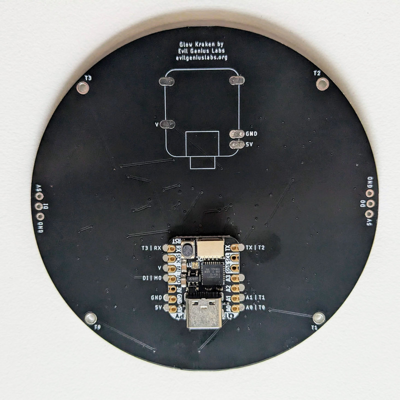
The Fully Assembled option includes all three PCBs, already assembled with M2 hardware and pre-programmed Adafruit QT Py SAMD21.
Open source touch demo: https://github.com/jasoncoon/kraken64-qt-py