Evil Genius Labs
Purveyor of finely hand-crafted pixels. ꩜
Purveyor of finely hand-crafted pixels. ꩜
For free shipping worldwide, you can order directly from OSH Park: https://oshpark.com/shared_projects/xeBcFP0G
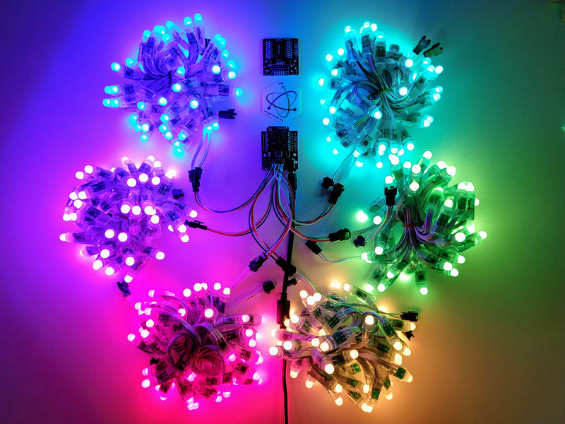
This is a shield/breakout for the Wemos D1 Mini (and D1 Mini Pro) ESP8266 board that makes it easy to control addressable RGB LEDs, such as WS2811, WS2812 (Adafruit NeoPixels), and APA102 (Adafruit DotStars). The Wemos D1 Mini is an excellent mini Wi-Fi development board, based on the ESP8266. I’ve used it extensively in development of addressable RGB LED art projects, such as my 6.5ft Rainbow Tree, Bloom v2, and Ducenti. This shield supports 6x parallel output.
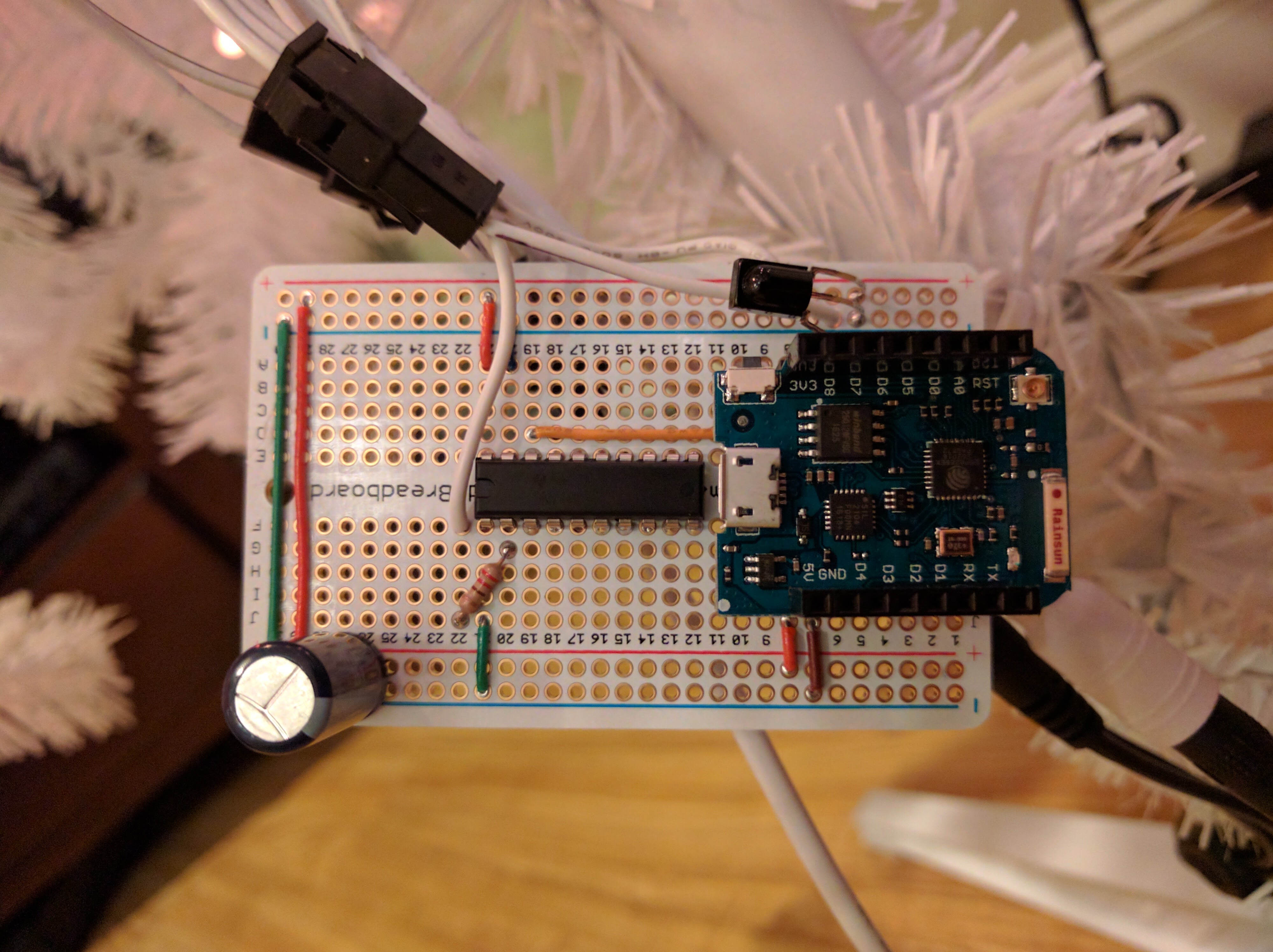
I made this shield because I was hand-wiring this same layout on perma-proto boards, which was time-consuming and unprofessional looking.
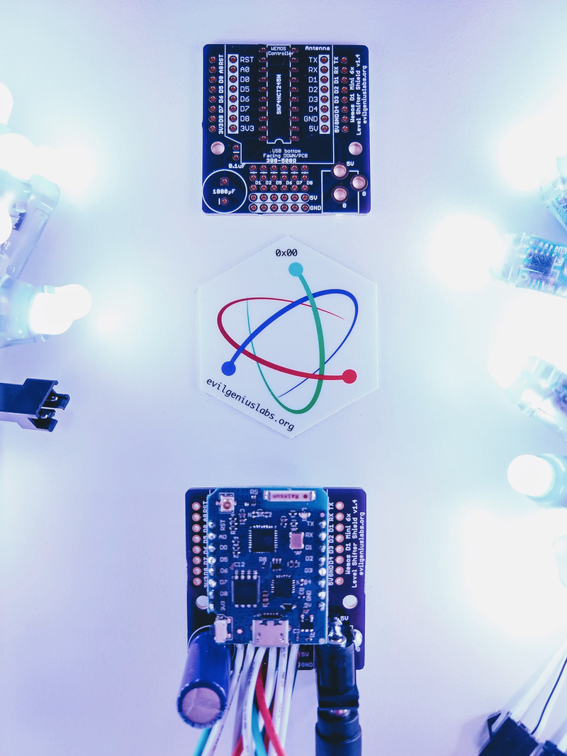
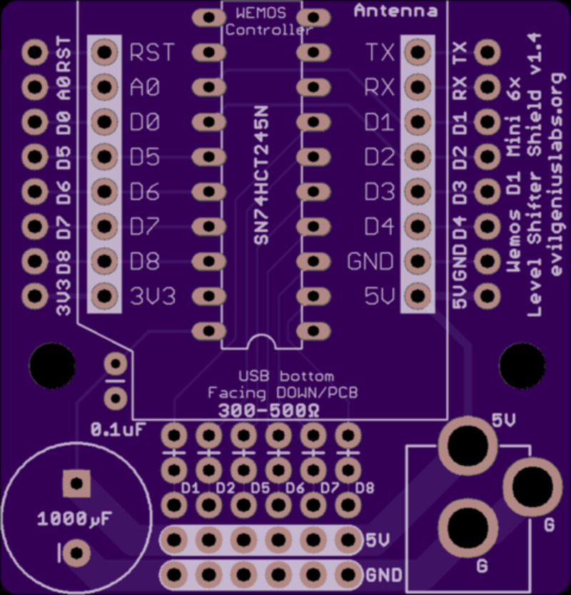
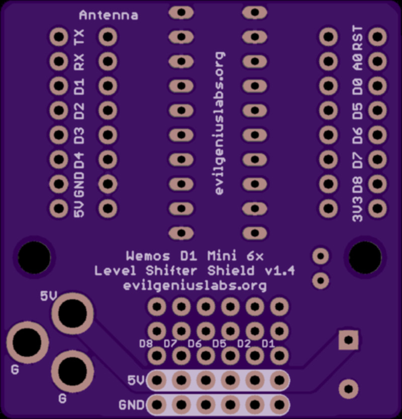
The shield includes a 74HCT245 level shifter, which is the most well-regarded high speed level shifter I’ve found. This shifts the 3.3V logic level of the ESP8266 to the 5V expected by addressable RGB LEDs. These projects often work fine without a level shifter, until they don’t.
Six digital output pins (D1, D2, D5, D6, D7, D8) are run through the level shifter. These pins support parallel output by the fantastic FastLED library.
The shield also includes data line resistors and a large 1000uF capacitor, as recommended when driving LEDs, especially when powering the microcontroller from the same power supply as a large number of LEDs.
The 90 mil, double-sided 5V and GND traces should be rated for up to ~12 amps. That’s enough for about 200 LEDs at max output (solid white, full brightness), and much more than 200 LEDs at lower output, lower brightness, and/or multicolor patterns. A barrel connector can be added to connect a power supply, but most are only rated for 2.5A (~50 LEDs at max output). For larger quantities, power should be connected to the PCB directly with large gauge wire, connected directly to the LEDs, and/or brightness should be limited in software. It is very important when using high current power supplies and large numbers of LEDs to watch for overheating on wiring, connectors, components, and the PCB.
Parts that are not included, but are required to assemble:
Wire/Connectors
OR
All of my projects lately have been driven by ESP8266 microcontrollers with Wi-Fi support. Following the best practice recommendations of using a fast level shifter, large capacitor, and resistors on the clock and data lines was resulting in a lot of wires on a large perma-proto board. I decided to design a PCB to make it cleaner and more compact.
It’s much smaller and easier to assemble, compared to the perma-proto boards I was building:
After trying a lot of different ESP8266 boards, I’ve found the Wemos D1 Mini to be great for the price. It includes an improved CP2104 USB-TO-UART adapter for more reliable, high-speed firmware and SPIFFs updates, larger (16MB) flash storage, etc.
Open source example firmware and web application: https://github.com/jasoncoon/esp8266-fastled-webserver/tree/parallel

Features:
Note: Double-check the position, alignment, and orientation of each component very carefully before soldering!
If you’re new to soldering, I highly recommend reading through a good soldering tutorial, such as the ones by Adafruit and SparkFun.
Insert the SN74HCT245N Level Shifter chip into the holes in the top side of the board, where indicated, with the indentation towards the bottom edge of the board. 
Flip the board over and solder one pin on the chip, pressing down on the PCB to ensure the chip is seated firmly.
Make sure the chip is still seated properly before proceeding to solder the rest of the pins.
Insert the 0.1uF capacitor, flip over and solder. 
Insert a 300 Ohm to 500 Ohm resistor in each set of holes for each output you plan to use. Bend one leg 180 degrees around, flat against the resistor body, and insert it vertically.
Flip the board over and solder each leg of each resistor.
Decide whether you’re going to use female headers, stacking female headers, or if you’re going to solder the Wemos directly to the level shifter shield PCB. I used single female headers so the Wemos would be removable, but still fairly low profile.
I used double-sided male headers in a small breadboard to hold the female headers correctly aligned while I soldered.


Insert the power barrel jack.
Flip the PCB over and solder it in.
The pads are very large, and connected to large ground and power planes on the board, so they might take a while to heat up before the solder starts to flow around the leads.
Insert the large 1000uF capacitor, make sure the negative leg of the capacitor is in the negative labeled hole in the PCB.
Flip the board over and solder one leg, making sure the capacitor is properly aligned before soldering the other leg.
Trim all the leads with a pair of wire cutters. Flush diagonal cutters work best.
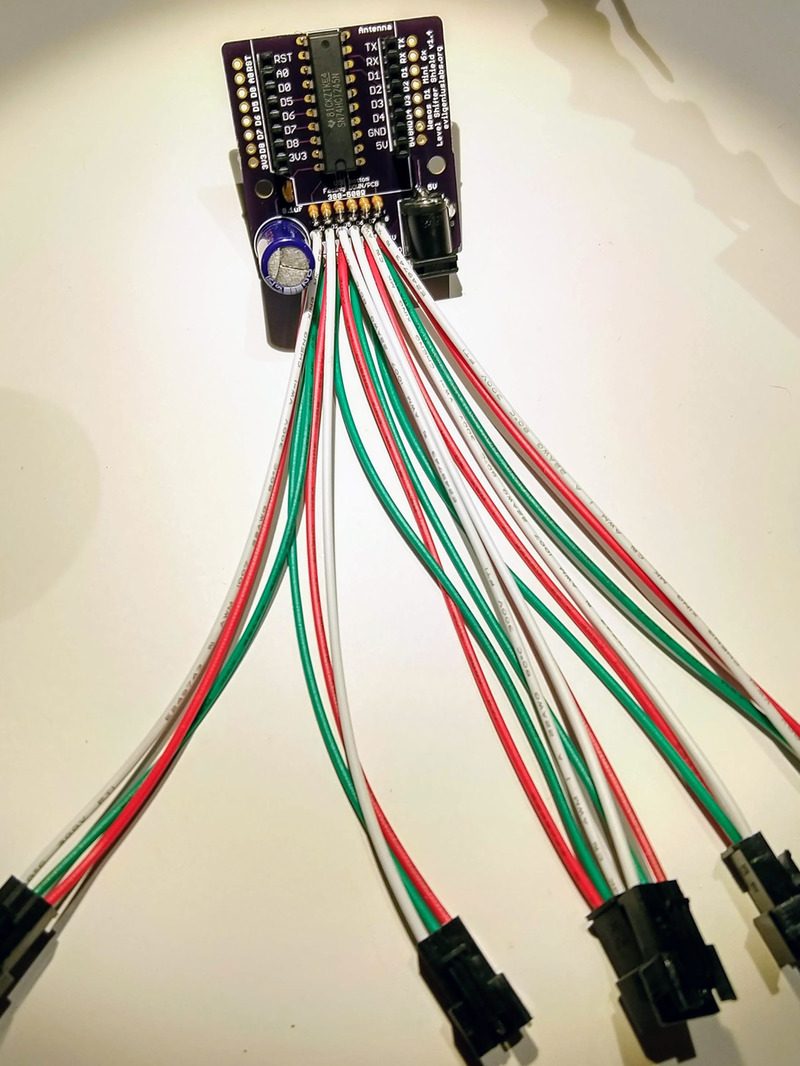
I use pre-assembled 3 pin JST-SM connectors to connect the LEDs.
If possible, use a PCB vise to hold the PCB vertically, and a helping hands tool to hold the wires as they’re soldered.
With a small amount of solder on the tip of the iron, heat the wire right on the bottom of the pad.
Melt a fair amount of solder on the wire and pad. The insulation on the wire may start to melt as the wire heats up. If so, push the wire through the hole, from the top towards the bottom, to ensure no wire is left exposed on top.
Repeat this process for the other wires.